Home
Uncategories
Diy Metal Detector Circuit : Pi Metal Detector Amplification Circuit Electrical Engineering Stack Exchange / The other day when i was searching instructables i come across on interesting and simple circuit for metal detector.
Diy Metal Detector Circuit : Pi Metal Detector Amplification Circuit Electrical Engineering Stack Exchange / The other day when i was searching instructables i come across on interesting and simple circuit for metal detector.
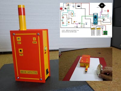
Diy Metal Detector Circuit : Pi Metal Detector Amplification Circuit Electrical Engineering Stack Exchange / The other day when i was searching instructables i come across on interesting and simple circuit for metal detector.. There are three main parts in the metal detector circuit: Some circuits would be illegal to operate in most countries and others are dangerous to construct and should not be attempted by the inexperienced. Now the two frequency will be different, there will be no cancelling and the radio produces a hissing sound. In this project, we are going to build a simple metal detector circuit using a bc548 transistor. The metal detector is built with one 100µh coil that has 40 mm in diameter and is made of 50 turns/0.4 mm wire.
Metal detector circuit diagrams and projects note that all these links are external and we cannot provide support on the circuits or offer any guarantees to their accuracy. In the circuit there is an rlc circuit formed by 47k resistor, 2.2µf capacitor, and 150turn inductor. How to build a cheap, light, but sturdy metal detector straight shaft; It is not suitable for buried coins discovery that is not sensitive enough but you can detect pirates treasures! This homemade metal detector circuit will help you find objects composed of materials with relatively high magnetic permeability.
Diy Metal Detector Using Arduino Step By Step Arduino Project Hub from hackster.imgix.net Search electronics kits and modules available in our store. If the coil detects the metals, then you are ready to take your new metal detector out and start looking for treasures. The circuit utilises two rf oscillators. Metal detector circuit diy metal detector project with pic12f1572 (or pic12f1840) microcontroller. This means a metal object is detected. Whether you're looking for a knife or a silver bracelet, this alert is what you're waiting for. The 1st probes were home made devices, cobbled together by enthusiasts, usually made from parts taken from hand held metal detectors of the type that are sold in diy stores. This rlc circuit is the metal detection part.
See bottom of description for the gold, coins and treasure ebook.
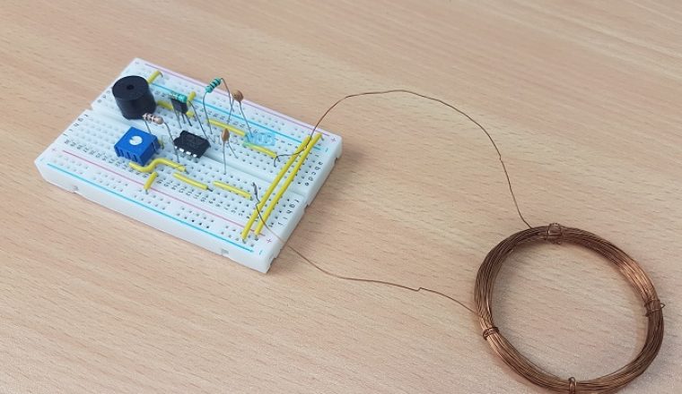
There are three main parts in the metal detector circuit: Whenever it senses any metal object near to it activates the proximity sensor. Whether you're looking for a knife or a silver bracelet, this alert is what you're waiting for. How to catch mice with just a glue trap and a cardboard box. When a metal objects are within this field, the detector gives an audible, and usually a visual, signal to alert you to the presence of metal. The is accomplished by closing the bipolar power transistor or mosfet that connects the coil with the power supply. This is yet another metal detector kit for electronics beginners. Now the two frequency will be different, there will be no cancelling and the radio produces a hissing sound. The heart of this diy metal detector circuit is the cs209a ic. After assembling the kit, if you take the kit close to a metal, the buzzer will turn on and the led will flash. Breakdown effect over the driver mosfet A normal metal detector only uses one oscillator, but this diy will need to make use of two different oscillators to detect a change in the note when metal is detected. It is build with 555, coil and few other components.
When the metal detector circuit is placed near to a metal object the inductance of its coil changes, and so do the frequency of oscillations. Cs209a has one oscillator wich forms a lc circuit, the inductance of the coil will change when it is near metal objects. Diy metal detector coil housing build; The metal detector is powered by 2 x 9v batteries, each of it charges with 15 ma. This rlc circuit is the metal detection part.
Free Circuits Metal Detector from lh4.googleusercontent.com This rlc circuit is the metal detection part. The detection cycle of pulse induction metal detectors starts right after the magnetic field has been turned of. Furthermore, the adjustment in the magnetic field produces an electric field. It is not suitable for buried coins discovery that is not sensitive enough but you can detect pirates treasures! Metal detector circuit diy metal detector project with pic12f1572 (or pic12f1840) microcontroller. In this project, we are going to build a simple metal detector circuit using a bc548 transistor. Once you have assembled your metal detector, you should test it. Metal detector circuit diagrams and projects note that all these links are external and we cannot provide support on the circuits or offer any guarantees to their accuracy.
The following article is made to simplify the basics of electronics.
Truly the best mouse trap i have seen. Take a 9 volt battery and connect it to the battery clip. Quate for all purposes in this metal detector circuit. This rlc circuit is the metal detection part. The circuit utilises two rf oscillators. A normal metal detector only uses one oscillator, but this diy will need to make use of two different oscillators to detect a change in the note when metal is detected. Some circuits would be illegal to operate in most countries and others are dangerous to construct and should not be attempted by the inexperienced. Metal detector circuit diy metal detector project with pic12f1572 (or pic12f1840) microcontroller. The frequencies of both oscillators are fixed at 5.5 mhz. Connecting the metal detector electronics together Now the two frequency will be different, there will be no cancelling and the radio produces a hissing sound. It is build with 555, coil and few other components. In the circuit there is an rlc circuit formed by 47k resistor, 2.2µf capacitor, and 150turn inductor.
Quate for all purposes in this metal detector circuit. See bottom of description for the gold, coins and treasure ebook. Whether you're looking for a knife or a silver bracelet, this alert is what you're waiting for. If the decay of the reflected pulse takes more than a few microseconds longer than normal, there is probably a metal object interfering with it. The 1st probes were home made devices, cobbled together by enthusiasts, usually made from parts taken from hand held metal detectors of the type that are sold in diy stores.
Metal Detector Circuit Diagram And Working from www.electronicshub.org The lc circuit, the proximity sensor, output led and the buzzer. Instructable that inspire me to do this project was this one. The is accomplished by closing the bipolar power transistor or mosfet that connects the coil with the power supply. In this project, we are going to build a simple metal detector circuit using a bc548 transistor. It is build with 555, coil and few other components. Whenever it senses any metal object near to it activates the proximity sensor. The lc circuit is the combination of an inductor and a capacitor in parallel. The sensitivity of the kit can be adjusted using the potentiometer.
How to catch mice with just a glue trap and a cardboard box.
Truly the best mouse trap i have seen. The main components of a simple metal detector are lc oscillator, proximity sensor, and an led or a buzzer. Diy metal detector coil housing build; This rlc circuit is the metal detection part. By comparing it to the expected length, the circuit can determine if another magnetic field has caused the reflected pulse to take longer to decay. These instruments function by sensing changes in magnetic waves caused by being in near proximity to a metallic object. A normal metal detector only uses one oscillator, but this diy will need to make use of two different oscillators to detect a change in the note when metal is detected. It is build with 555, coil and few other components. This homemade metal detector circuit will help you find objects composed of materials with relatively high magnetic permeability. The type of device that is used for detecting nails, pipes, or wires in floorboards. Quate for all purposes in this metal detector circuit. If the decay of the reflected pulse takes more than a few microseconds longer than normal, there is probably a metal object interfering with it. How to catch mice with just a glue trap and a cardboard box.
In the circuit there is an rlc circuit formed by 47k resistor, 22µf capacitor, and 150turn inductor diy metal detector. Once you have assembled your metal detector, you should test it.

0 Comments:
Posting Komentar